
·
A sunlight-readable display must deliver the same image on a pole at noon as it does on an engineering bench. Most fail this because they rely on a single brightness setting. An overcast day will have between 1,000- 4,000 lux on a screen. In direct sunlight, you will get 80,000-200,000lux. Outdoor readability is defined when writing the spec; you cannot increase the backlight to improve it.
This guide shows you how to design a display that is readable in sunlight.
Sunlight Readable Display Specification at a Glance
If the screen’s light output exceeds the reflected sunlight, it will be readable in sunlight. This factor is called the ambient contrast ratio and matters more than brightness. Direct sunlight can reach 80,000 to 200,000 lux, and a typical screen at 250 to 450 nits would be washed out. An ambient contrast ratio of 5:1 is often quoted as the minimum requirement for a screen to be readable in daylight.
Specify the screen as an overall system. Consider design light level, contrast ratio, reflectivity, bonding method, touch performance with gloves/water, and thermal considerations. Also specify the viewing angle, polarised sunglasses, backlight end-of-life brightness, and screen life. E3 Displays starts with an off-the-shelf panel and includes the brightness, bonding, surface treatments, and touch required for each application.
What Outdoor Readability Actually Depends On
Brightness alone does not decide visibility
Datasheets quote contrast ratios measured in dark environments. So you won’t get that 1,000:1 ratio unless absolutely no light hits the panel.
Outside, ambient light will reflect off the front of the panel. This means that both the white and black portions of the image will be brighter. The black areas become much brighter, and the image becomes flat and grey.
Ambient contrast ratio is the real measure
Ambient contrast ratio (ACR) captures this effect. It compares white and black luminance after reflected light is added to each:
ACR = (L white + R × E ÷ π) ÷ (L black + R × E ÷ π)
L white and L black are the display’s own white and black luminance in nits. R is the surface reflectance, and E is the ambient illuminance in lux. The term R × E ÷ π is the reflected luminance the viewer sees. Researchers at the National Institute of Standards and Technology (NIST) have published methods for measuring this contrast in daylight.
Reflected light competes with emitted light
The table below runs the formula for a panel with 1,000:1 native contrast in 100,000 lux of direct sun. It is a simplified illustration. It treats reflectance as one value, while real measurements separate mirror-like and diffuse reflection.
| Surface reflectance | Reflected luminance (nits) | ACR at 1,000 nits | ACR at 2,500 nits |
|---|---|---|---|
| 12% | 3,820 | 1.3:1 | 1.7:1 |
| 4% | 1,273 | 1.8:1 | 3.0:1 |
| 0.5% | 159 | 7.2:1 | 16.4:1 |
A 1,000-nit display at 0.5% reflectance outperforms a 2,500-nit display at 4%. Reflection control also adds no backlight power and no heat. Reflective and transflective panels take this further by using ambient light rather than fighting it, as our guide to reflective and transflective LCD monitor options explains.
Brightness and Where the Useful Range Sits
Indoor panels versus outdoor panels
Typically, office and consumer panels will have a brightness of 250 to 450 nits. Outdoor panels will generally be 800/1000 nits+. E3 Displays can work with displays up to 2500 nits. Screens can range from 1 inch to 100 inches. This is just the panel itself. Anything on top of the panel, such as cover glass, touch sensor, and filters, will reduce the light hitting the eye.
Shade, partial sun, and direct sun are different cases
Outdoor ambient light spans two orders of magnitude. The ranges below come from the same patent cited earlier.
| Condition | Typical illuminance (lux) |
|---|---|
| Overcast day | 1,000 to 4,000 |
| Full daylight, no direct sun on the screen | 8,000 to 30,000 |
| Direct sunlight | 80,000 to 200,000 |
The middle row is used for most of the day, with a canopy-covered screen. The lowest row will be used at noon with an open face. The specification should include the worst-case scenario the screen will suffer. Also include whether the screen can receive direct sunlight.
Why over-specifying brightness backfires
Going beyond what is required will cause issues. Increasing the current to the LEDs increases power usage and generates more heat behind the panel. This will also accelerate backlight degradation.
A very bright screen will cause glare at night if it can’t be dimmed. The specification should include the dimming range. Passive enhancements cut the demand before dimming does. See which treatments reduce backlight load without adding power.
In one marine project with E3 Displays, the backlight could reach 1500 nits during the day and then smoothly dim to 1 nit at night.
High Brightness or Transflective
Two design routes lead to daylight readability. A high-brightness backlight overpowers ambient light. A transflective panel reflects ambient light off a layer behind the pixels. It uses the sun instead of fighting it. The right route depends on the power source and the lighting range.
| Factor | High-brightness backlight | Transflective panel |
|---|---|---|
| Readability as sunlight increases | Falls, unless brightness rises with it | Improves |
| Backlight power | High | Low, and the backlight can switch off in daylight |
| Heat added behind the panel | Significant | Minimal |
| Low-light performance | Strong | Weaker, because less backlight passes through |
| Typical fit | Mains-powered signage, kiosks, vehicle and marine displays | Battery-powered handhelds, meters and solar-powered units |
On battery equipment, a third option exists: a pixel that holds its image without refreshing. See where 1-bit memory beats a transflective TFT. E3 Displays offers both routes through its all-light readability displays, including transflective and reflective polarizer options. Optical bonding and contrast-enhancing films improve both approaches.
Reflection and the Surface Stack
Anti-glare versus anti-reflective
AG etching reduces glare by scattering reflections. This breaks up the bright circular image of the sun but produces a hazy image and can blur fine text.
AR coatings reduce reflected light using interference. A good AR coating will reduce the percentage of light reflected from the outer surface to around 0.2%. Our look at five optical bonding advantages covers what bonding adds alongside surface coatings. This is a significant improvement when compared to a normal piece of glass, which can reflect up to 4%.
Some stacks will use an AR coating with a light AG coating. E3 Displays applies AR, AG, and anti-smudge treatments through coated glass or anti-reflective film lamination.
Where reflections come from in an air-gap assembly
Each glass-air boundary reflects about 4% of incoming light. A cover glass mounted over an LCD with an air gap has three such boundaries. Together, the three reflect about 12%.
| Front-of-screen configuration | Total specular reflectance | Contrast ratio at 2,000 fc |
|---|---|---|
| Unbonded plain glass | About 12% | 1.31:1 |
| Unbonded AR glass | About 8.2% | 1.45:1 |
| Optically bonded plain glass | About 4% | 1.93:1 |
| Optically bonded AR glass | About 0.2% | 18.37:1 |
To match the bonded AR result with unbonded AR glass, the study calculated that the display would need 2,969 fL. That is roughly 10,000 nits. With real internal layers such as the color filter included, the bonded AR stack still held about 6.6:1.
Every added layer costs contrast
Touch sensors, heating glass, filters, and protective windows add extra surfaces. These are all mounted using edge tape, leaving an air gap. This causes reflection. Optically bonded adhesive can fill the air gaps. This has a refractive index very similar to glass. E3 Displays uses liquid optically clear adhesive (LOCA), an adhesive sheet (OCA), or a combination of both. Air bonding bonds only the edges and leaves an air gap, causing reflections. Our article on how touch panels and cover glass affect readability quantifies what each added surface costs in reflective mode.
Heat, the Constraint Most Projects Underestimate
Solar load on the front, backlight load behind
The display will have two heat sources. The first is the front of the display. Most of the sunlight will be absorbed rather than reflected. This will cause a heat buildup within the panel. The second source is the backlight.
A brighter backlight increases heat. This means there are two heat sources. The display may feel cool indoors, but it can become very hot outside. Even on a mild day. So the thermal design must consider both heat sources from the start.
What heat does to an LCD
The LCD only functions within a certain temperature range. Once the temperature exceeds the clearing point, it becomes isotropic and stops controlling the light. This means the LCD will turn black and become unreadable until it cools. Solar loading can heat the liquid crystal beyond the clearing point, so even if the air is well below the clearing point, the temperature can rise above the range. Air gaps will make this worse, as the area behind the touch sensor will act as a greenhouse.
The LCD will suffer more gradual damage due to heating. The LCD backlight life will be reduced because the LEDs run hotter. UV radiation will break down the adhesives, seals, and polarizers. Method 505 has a separate test for this degradation.
Passive and active approaches
Most outdoor thermal designs start passive:
- A hood or shade structure, which cuts solar gain at the source
- Optical bonding, which lets heat leave through the front glass instead of sitting in an air gap
- IR-rejecting layers or hot mirrors bonded into the stack to turn back solar heat
- A chassis or heat spreader that conducts backlight heat away from the panel
- Ambient light sensing, so the backlight runs at full power only when needed
- Wide temperature displays chosen for the temperature at the panel, not just the air around it
Fans and forced air come next. Moving air removes more heat but complicates sealing. Active cooling suits enclosures that already have filtered airflow.
Adding Touch Without Losing Readability
A touch sensor is an optical decision
A touch sensor adds an extra layer (and often two extra surfaces) to the system. This can negate much of the reflectance improvement achieved above for a sunlight-readable display.
Bonding the touch sensor to the LCD and cover lens eliminates internal surfaces and parallax issues between where the touch occurs and the underlying image. E3 Displays integrates touch panels and PCAP touchscreens into bonded assemblies.
Cover lens thickness and surface treatment
Thicker, stronger cover glass raises impact tolerance. It also moves the finger farther from the sensor, affecting touch accuracy. AG finishes reduce glare and fingerprints but add slight haze. Engineers should choose glass, thickness, finish, and controller tuning as one decision.
Gloves, rain and standing water
Outdoor users may be using gloves. The screens are also likely to be wet. Projected capacitive (PCAP) controllers can be configured to handle both issues. Resistive sensors register a gloved press through pressure, but PCAP has replaced resistive on most industrial equipment because it adds fewer layers and survives longer. An E3 Displays Marine project involved setting the touch controller firmware to ignore water droplets and allow users to use gloves and fingers. The requirement should specify the type of gloves used and whether the screen will be exposed to water. This will affect the controller’s settings.
Enclosure, Mounting and Viewing Angle

Orientation relative to the sun path
Where a screen points matters as much as what sits inside it. In the Northern Hemisphere, a north-facing screen avoids most direct sun on its face.
A south-facing screen takes the full midday load. Readability fails worst when the sun’s mirror reflection lands in the viewer’s eyes. A small tilt can move that reflection out of the viewing zone.
Shading and hooding
A hood is often the lowest-cost item on the list. It blocks direct sun on the face, cuts solar heat, and reduces reflection in one step. The trade-off is a narrower side viewing angle.
Sealing against dust and moisture
Specify the IP rating per IEC 60529 for the front face and the whole housing. A front-sealed and fully sealed unit are two distinct products. Using optical bonding to fill the air gap within the stack can cause humid air to gather and condense as temperatures change.
Off-axis contrast and polarized sunglasses
Outdoor viewers rarely stand square to the screen. The requirement should give contrast at the angles where users actually stand, sit, or drive. Wide viewing angle displays widen that range.
Polarized sunglasses add a second issue. LCDs emit polarized light, so polarized lenses can black out the screen at certain angles. A front polarizer set at 45 degrees, or an added retarder film, prevents a full blackout. Polarizer orientation is one of eleven decisions that belong in the spec before a panel is selected.
Lifetime and Availability

Backlight degradation over service life
LED backlights typically won’t completely fail but will dim over time. Datasheets often describe this in terms of half-life, or how long the backlight will run before it reduces to half brightness. Increasing the backlight’s workload and temperature will increase this degradation.
A display that is bright enough on day one may not be bright enough after 5 years. The requirement should include the display’s minimum brightness at the end of its service life.
Component availability belongs in the original spec
Many outdoor programs outlast the production life of the panels inside them. A mid-program panel change can force new optical, thermal, and environmental qualification.
E3 Displays manages component lifecycle and obsolescence planning so programs avoid surprise redesigns. Supply period and change notification are worth settling before panel selection, not after.
How to Verify Readability Before Production
A specification helps only if you test the prototype against it. Three checks catch most outdoor failures before units ship.
Measure ambient contrast, not just brightness
Use a luminance meter and calibrated light source to measure white and black luminance at a fixed illuminance. Run the test on the final assembly, including the cover glass, touch sensor, and any filters.
Run a solar load test on the full assembly
The oven test heats the unit evenly with air, whereas sunlight heats it from one side, causing temperature gradients. Use MIL-STD-810 Method 505 Procedure I to cycle simulated sunlight and determine the temperature increase over ambient conditions. The panel will then be at the true maximum operating temperature. This method can be used in non-defense programs.
Trial units at the actual site
Lab tests cannot reproduce every reflection path, tilt, or viewer position. A short field trial at the worst-case site and hour shows how the screen reads in practice. It also confirms dimming behavior, glove input, and readability through polarized sunglasses.
How Requirements Differ by Application
The same principles apply everywhere, but the weighting changes with the application.
| Application | Readability driver | Specification focus |
|---|---|---|
| Marine bridges and decks | Sun on the screen, salt spray, night operation | Bonding, AR surface, wide dimming range, wet and gloved touch |
| Avionics cockpits | Very high ambient light through the canopy, night vision compatibility | Low reflectance, high luminance, NVIS filters |
| Outdoor digital signage and kiosks | Long daily run time in fixed sun exposure | Thermal path, hooding, backlight life, orientation |
| Industrial HMI and vehicles | Glare through windows, vibration, gloved operators | Bonding for shock and glare, PCAP tuning, wide temperature range |
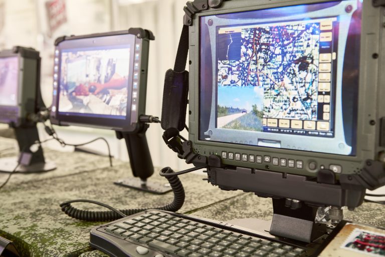
The 2013 Information Display study cites up to 8,000 fc of diffuse light in commercial avionics cockpits. Displays for military platforms follow additional requirements on rugged displays and night vision compatibility. On those platforms, NVIS filtering blocks the infrared output that would otherwise bloom through night vision goggles.
Case Study: A Bridge-Mounted Marine Display
The challenge
A marine electronics manufacturer was revamping one of its bridge-mounted chart and sonar units. They needed a medium-sized display and touchscreen that could be viewed in bright sunlight and low light conditions. The display could not lose any color or contrast. The touchscreen needed to be UV-, water-spray-, and glove-resistant. The assembly also needed to cope with solar loading, heat, and humidity. Long life and competitive pricing were required.
The approach
E3 Displays worked with a major LCD maker to select an existing base LCD for the application. The team designed a high-brightness LED backlight and changed the internal films. It specified a touch panel with high-temperature, UV-resistant materials and an AR front surface. The team then fully optically bonded the touch panel to the LCD.
The outcome
The assembly measured 1,500 nits at low power and heat. It added no heat load inside the customer’s unit. The backlight driver dims smoothly down to 1 nit for night use. The bond reduced reflective surfaces and removed the gap where condensation could form. The full write-up is in the E3 Displays marine case study.
Common Misconceptions About Sunlight Readable Displays
- “More nits solve the problem.” Reflection often matters more, as the contrast table above shows.
- “The datasheet contrast ratio predicts outdoor performance.” It is measured in the dark and says little about sunlight.
- “Any outdoor display can sit in full sun all day.” Solar load can push a panel past its clearing point.
- “Optical bonding is only for military hardware.” Bonded displays are widely used in marine, signage, medical and industrial products.
A Specification Checklist for Engineering Teams
These 15 items cover the decisions above. Each one belongs in the written requirements before panel selection.
- Design illuminance at the screen face in lux, and whether direct sun reaches it
- Minimum ambient contrast ratio at that illuminance, and the measurement method
- White luminance in nits, measured at the front of the finished assembly
- Total front-surface reflectance of the finished stack, specular and diffuse
- Surface treatment: AR, AG, anti-smudge, or a combination
- Bonding method: OCA, LOCA, hybrid, or none
- Touch technology, cover lens thickness, and glove and water requirements
- Viewing cone, off-axis contrast, and polarizer orientation for polarized eyewear
- Operating temperature range at the panel, including solar load
- Clearing point margin above the worst-case panel temperature
- Thermal path: mounting, venting or sealing, and whether active cooling is allowed
- Dimming range and ambient light sensing for night use
- Backlight half-brightness life at operating current and temperature, plus end-of-life luminance
- IP rating for the front face and the full enclosure, plus UV exposure limits
- Panel supply period and change-notification terms
Putting the Specification Together
Outdoor legibility depends on early design decisions. A bright, air-gap-backed panel can be outperformed by a dull, bonded panel. A bright bonded panel may still fail under solar loading, causing it to rise above its clearing point. The system must define brightness, reflectivity, thermal, tactile, enclosure, and life.
E3 Displays starts from off-the-shelf panels and adds the brightness, bonding, surface treatments, and touch integration each application needs. To review a requirement or a sunlight-readable display panel shortlist, contact an E3 Displays engineer.